Our requirement was to develop a device identification of specific vehicle motion patterns. Also it is needed to sync the data frequently with a mobile application (about once in a week) to get the data to the mobile application for further analysis. As the data is read once in a week. It is also needed to implement a saving mechanism. Also, the device is needed to be as small as possible, so that it is similar to a tag that can be placed in a fixed position in the vehicle. Another thing that we needed to consider was the power consumption. Even though the device uses a rechargeable battery, the power consumption needs to be ultra low for the following 2 reasons. One is that the battery size can be reduced as small as possible if we have better power optimization and the second reason is that the user does not need to check on the battery charge level frequently if the device can stay for months without being recharged.
So, we considered the above things to start with the component selection, pcb design and determining the algorithm for the firmware. We decided on the main components of the system as follows.
- Microcontroller. Microcontroller is used because it is a wearable device which needs to be small and also there are microcontrollers that can support running neural network inference.
- IMU (6 Axis accelerometer, that is an accelerometer and gyroscope). IMU is the only available option for detecting motion in wearable devices. Also we used a gyroscope for the reason that it can be used to identify events such as turns or tilts.
- Charging IC.
- Regulator.
- BLE transmission component.
- Indications. We decided to have no indications as there is no requirement for any live indications and also to save power. LED indications will work during BLE advertisement and communication time only.
Then we decided on the following things.
Microcontroller Selection
We planned to use an STM32WB55CG microcontroller for the processing unit. The microcontroller is selected for the following reasons.
- This series of microcontrollers are ultra low power microcontrollers that support several low power modes ranging from run mode that runs in 1-15 mA current (in 3 - 3.3 V) supply to shutdown mode that runs with less than 50 nA in shutdown mode. We have several options for functionality vs power consumption in which we can tune our device.
- BLE was selected as the communication interface as it is the lowest power communication interface that can be used. As BLE is also needed, the microcontroller which also can work as a BLE transceiver is an added advantage as it can help to reduce PCB size . Another advantage is that low power BLE advertising is supported in the microcontroller, consuming less than 10 MicroAmperes during BLE communication.
- Another advantage of using this microcontroller is that this microcontroller series can support running neural networks. Also microcontroller manufacturers provide tools for converting a tensorflow or keras model into a library that can be run in the microcontroller.
IMU Selection
When we tried to select an IMU, we found several features in the existing IMUs that can be useful for our application.
- Detection of some predefined activities such as tilt detection, step counting and detection based on accelerometer or gyroscope value threshold or gradient threshold.
- Machine learning core which users can train by providing data related to different patterns that need to be detected.
LSM6DSOX is selected as the IMU because it possesses the above 2 features. In addition, it is also an ultra low power consuming IMU, consuming about 600 uA in high performance mode and consuming under 50 uA in lowest power mode.
Also we found there were no specific IMUs that are custom made for this application, we need to use one of the above 2 features of the IMU or directly use IMU in interrupt mode.
Regulator Selection
The selection should be a high efficiency switching regulator or a low dropout (high efficiency) linear regulator according to the operating voltage of the system, battery voltage. Commonly, for small size wearable or portable devices, mostly linear dropout linear regulators are used. There are 2 main reasons for this. One reason is that the noise from switching regulators can affect the functionality of other components in the system. The second reason is that the difference between the battery voltage and the operating voltage is low in the systems working with batteries of 3 V or 3.7 V (Most devices of the above kind use batteries in the voltage range). Therefore, LDO can be used with sufficient efficiency. According to this we selected the LDK130 3.3 V regulator. Note - Charging IC selection is not described in this article because of the reason that it does not affect the power consumption as well as the size of the device.
Options that we considered for the implementation of firmware with needed accuracy and minimum power consumption
Option 1
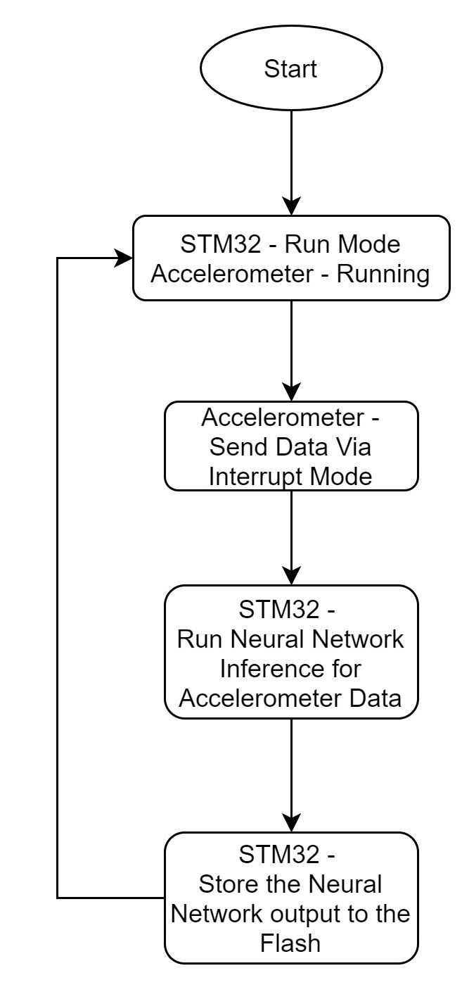
This option is to set the IMU in interrupt mode and to process the data from the IMU and run neural network inference in the IMU data continuously. This option is the most accurate option using the microcontroller and an IMU but, the power consumption of the option would be high due to the microcontroller always being in run mode to process IMU data. This image shows the basic flow diagram of option 1.
Option 2
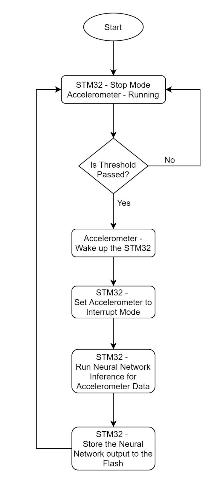
The idea behind option 2 is to power optimize option 1 using the threshold passing detection feature of the accelerometer. Here, the microcontroller will be in stop mode and the accelerometer will be running in low power mode when the device is not in motion. For a beginning motion pattern, the acceleration value should be greater than a particular value. Here the IMU will send an interrupt to wake up the microcontroller and the microcontroller will do the same thing as option 1 to detect the pattern. When the motion is completed, the microcontroller will set the accelerometer again into threshold mode and microcontroller will go to stop mode. This can reduce the power consumption as the microcontroller will be in stop mode unless there is significant motion
Option 3
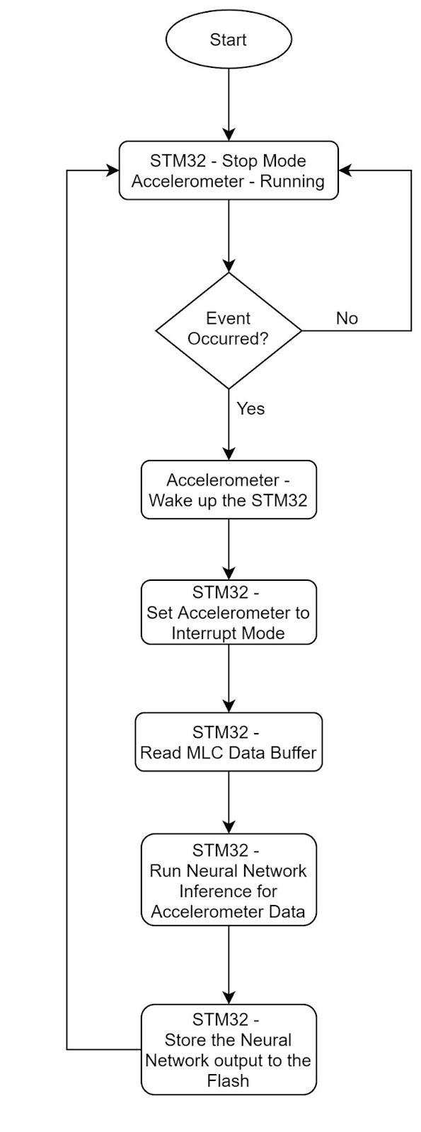
The next option is to use the machine learning core trained with the beginning data of the motion pattern so that the machine learning core sends an interrupt to the microcontroller to wake the microcontroller instead of the threshold in option 3. The only difference of this to option 2 is using the machine learning core instead of threshold. Here the waking up of the microcontroller during unrelated motion is prevented and power consumption is further reduced
Option 4
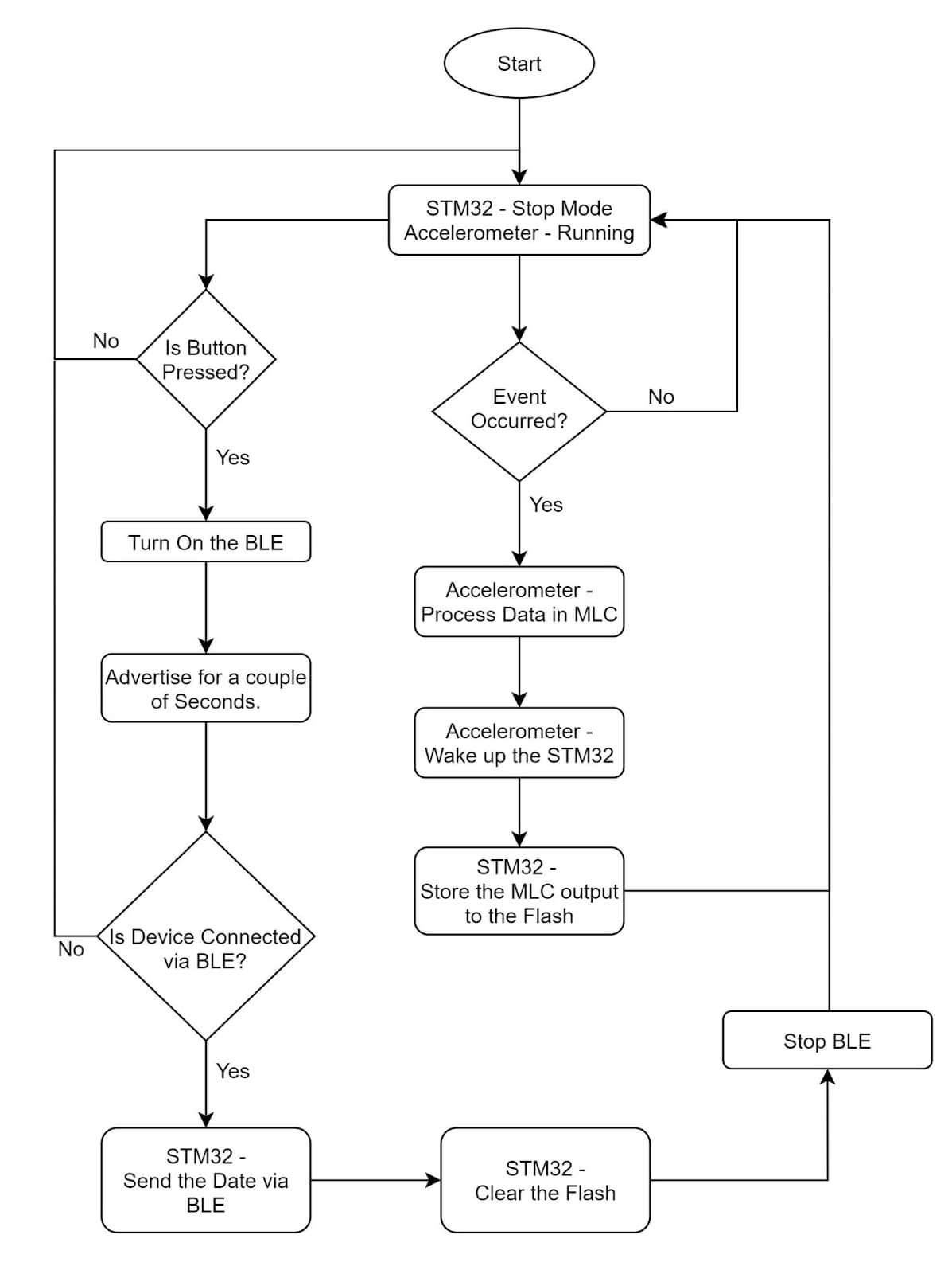
The next option is to run the complete motion detection at the IMU using MLC and then to wake up the microcontroller after detection just to store data only and go to stop mode again. This is the most power efficient option as it uses the microcontroller only during the motion save process
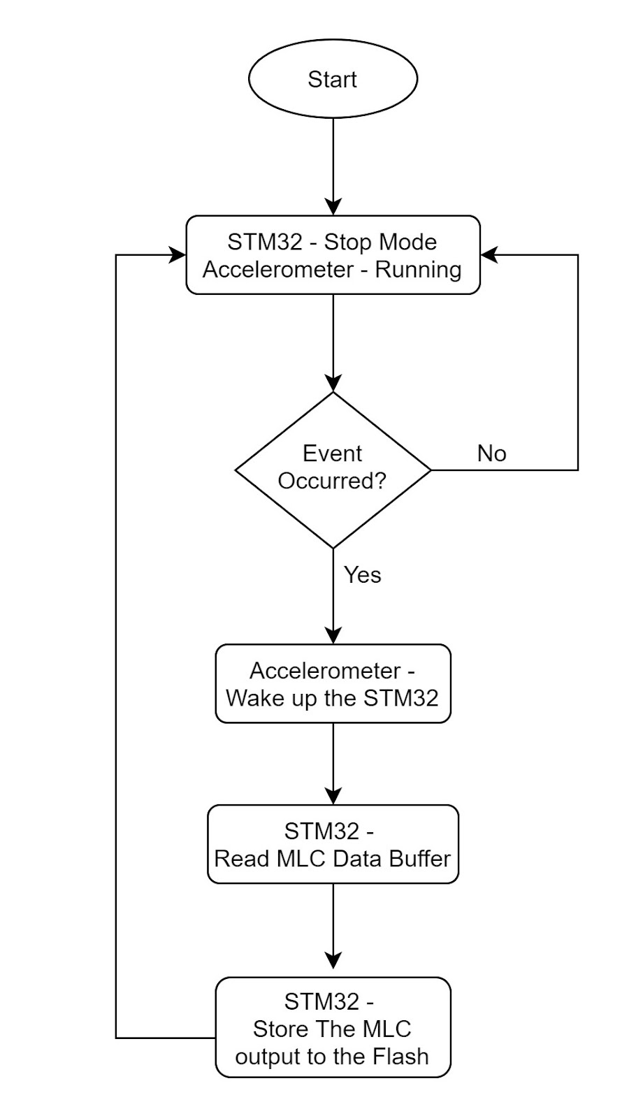
When we compare the 4 methods in general, the accuracy of Options 1 and 2 are almost equal. Option 3 is slightly less accurate than Options 1 and 2 because there can be false negative identifications in MLC for the beginning pattern. Option 4 is less accurate than the other 3 options.
When considering the power consumption, the order is, power consumption of, Option 4 < Option 3 < Option 2 < Option 1.
Hence, our choice needs to be an option that is a trade off between power consumption and accuracy. For this particular requirement, we need to identify a single pattern each time and also patterns are mostly less than 5 s long and the number of patterns that need to be identified is also 5. Also, for this application, the patterns needed to be detected have a not so relationship with IMU values, so we decided to first go with Option 4 and then try Option 3 depending on the accuracy that we can get with Option 4.
Data Collection Procedure
For the data collection procedure we collected data at a data rate of 52 Hz for the needed motion patterns as well as null data (data during not any of the motion patterns). We made another firmware to collect data and we did this instead of the specific data collection methods for MLS. The reason was to use this data collection procedure to collect data and use it with all the other 4 options (For this requirement our approach is using Option 4 or 3 but, we made data collection firmware for the reason that we may need Option 1 or 2 for similar requirements in future.
The data collection process is as follows.
It is better when the data collection is done with the same device that is used for identification (the pattern identification device). In the data collecting process data is collected through the microcontroller and sent to the app running on a mobile phone through bluetooth. In the data collection process, there needs to be a different firmware as the microcontroller should be in run mode to continuously get data and send through BLE. Also IMU will also be in continuous data mode and it will send interrupts according to the output data rate(ODR) configured in it by the microcontroller. For example, if the IMU is set for ODR of 52 Hz, the IMU will get 52 readings per second. So, the IMU will be sending 52 interrupts to the microcontroller, that is, every time the IMU data is ready. When the microcontroller gets the interrupt signal it reads the IMU data buffer immediately and sends the data to the mobile application over BLE immediately. This is the process to collect data. Data will be collected while doing/not doing the required motion.
Results
According to the collected data, we were able to get the required accuracy for this particular requirement in identifying the following patterns.
So, Option 4 was finalised.
Other things apart from the MLC and component selection that are done for power optimization
- Disabling all the peripherals when going to stop mode.
- Disabling the BLE processor when BLE is not used.
- Also, to reduce the power consumption due to BLE advertisement, BLE advertisement is enabled only for 1 minute after the BLE button is pressed by the user. If the mobile phone is connected during advertising time the pattern data can be transferred to the mobile application. If the mobile app is not connected within the time, the device will stop advertising.
Final firmware is developed combining the option 4 with BLE and adding the other power optimization techniques mentioned above (Here is the the final flow diagram).
General Limitations for similar applications
Complexity and the number of possible patterns to detect are limited due to memory limitations of the microcontroller and MLC.
Note - Instead of stop mode, shutdown mode can be used in the same way. If shutdown mode is used, the microcontroller will completely shut down and will start the firmware similar to a hardware reset and will do the necessary processing. Shutdown mode is not always used with similar applications if we need indications shown to the user on a frequent basis. Otherwise shutdown mode can be a good option to reduce power consumption.
Find the AIoT page that focuses on Senzmate's AI and IoT.
